The idea of this project was to learn the basics of electricity and coding and then make something using an Arduino. To learn the basics of electricity, we first used batteries and light bulbs to understand current, voltage, and resistance and how they behave in different circuits. We then moved on to using breadboards and smaller electronic components to further our understanding of this. Using the breadboards also introduced us to many other electronic components such as LEDs and potentiometers. After that, we started to learn coding and using even more complicated components with Arduinos.
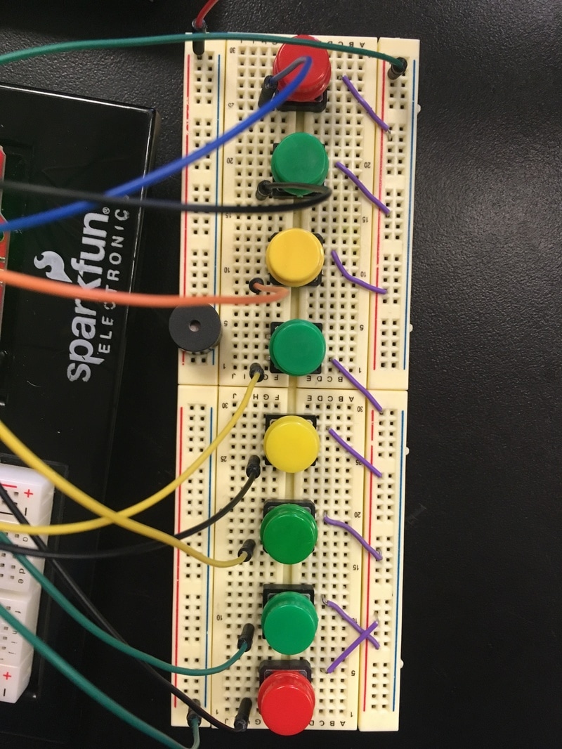
The first electricity experiments were done using standard 1.5V batteries, incandescent bulbs, and alligator clips. We first figured out how to light a light bulb and then observed what happened when we added a second bulb at different points in the circuit. With this we were able to define what a circuit is. Our final definition was that a circuit is a loop of conductive material from one terminal to the other. This means that a circuit has to be a loop and has to go from positive to negative. Some more experiments eventually showed us that there are two types of circuits, a series circuit and a parallel circuit. A series circuit is when the loop of electricity goes through all of the components, or when the components are connected one after the other. A parallel circuit actually consists of two loops with the components on them that come apart and then rejoin at the battery, hence the name parallel circuit. using the light bulbs, we observed that in a series circuit, if two bulbs were hooked up, they would both be half as bright as a single bulb. In a parallel circuit however, both bulbs were the same brightness as a single bulb. This led us to understand how current worked in a series circuit, because we knew that We then were also introduced to resistance, which was something that we found to be present in the bulbs that we had been using which decreased the resistance in a circuit as more was added. We added more resistance into a circuit using nichrome wire, which has more and more resistance the longer it is. We saw that adding more resistance lowered the current because the bulb would get less bright. We then observed that in a series circuit, multiple pieces of wire would just add up to give a total resistance (we didn't have an actual way to measure the resistance yet, so we just used the length of the wire in centimeters). This meant that in a series circuit, the total resistance = resistance 1 + resistance 2 + resistance 3... It was a little more complicated in parallel circuits though. After some testing we saw that in a parallel circuit, the the total resistance = 1/resistance 1 + 1/resistance 2. After understanding this we went on to using breadboards for our experiments. A breadboard is a board with many small holes in it, the holes form rows that are connected with conductive material. They are great for making temporary circuits with ease. We also used multimeters, which allowed us to measure the voltage, resistance and current of circuits and components. We were then introduced to Ohm's law, which states that voltage = current X resistance in a circuit. This was seen earlier when we saw that current and resistance are inversely proportional. Knowing that the batteries we used were 9 volts, if we had the current of the circuit, we could solve for the total resistance, and vice versa. Using the multimeters and breadboards, we then proofed Ohm's law. We then proofed other smaller theorems, such as In, series, voltage splits in proportion to resistance and current is the same through the entire circuit. We were then introduced to potentiometers, which are a form of variable resistor, meaning they are a resistor whose resistance can be changed. Then we used capacitors, which are basically small batteries that hold, and then release charge. After that we lit an LED. Then we had to set up a complex circuit to make sure that we were able to understand circuit diagrams and do that. Then, we moved on to the Arduinos. An Arduino is a small circuit board to which a breadboard circuit can be connected. It is then connected to a computer and code can be written for it. This allowed us to make much more complex things. First, we made a set of blinking LEDs. Then we connected those to the output of a potentiometer. For each experiment, we learned a lot about the code to. After those, we learned how to control an RGB LED. Then we moved on to input devices such as buttons, photoresistors, flex sensors, and temperature sensors. Then we were introduced to motors, servos, buzzers and more complex components like relays, shift registers, and LCD displays. when it came time for us to make our own circuit and code, we decided to make a piano. For the inputs, we used eight buttons and the output was a buzzer. Each button was supposed to play a tone on a major scale. To play chromatic notes, our idea was that pushing down two buttons would play the note in between them.
The first electricity experiments were done using standard 1.5V batteries, incandescent bulbs, and alligator clips. We first figured out how to light a light bulb and then observed what happened when we added a second bulb at different points in the circuit. With this we were able to define what a circuit is. Our final definition was that a circuit is a loop of conductive material from one terminal to the other. This means that a circuit has to be a loop and has to go from positive to negative. Some more experiments eventually showed us that there are two types of circuits, a series circuit and a parallel circuit. A series circuit is when the loop of electricity goes through all of the components, or when the components are connected one after the other. A parallel circuit actually consists of two loops with the components on them that come apart and then rejoin at the battery, hence the name parallel circuit. using the light bulbs, we observed that in a series circuit, if two bulbs were hooked up, they would both be half as bright as a single bulb. In a parallel circuit however, both bulbs were the same brightness as a single bulb. This led us to understand how current worked in a series circuit, because we knew that We then were also introduced to resistance, which was something that we found to be present in the bulbs that we had been using which decreased the resistance in a circuit as more was added. We added more resistance into a circuit using nichrome wire, which has more and more resistance the longer it is. We saw that adding more resistance lowered the current because the bulb would get less bright. We then observed that in a series circuit, multiple pieces of wire would just add up to give a total resistance (we didn't have an actual way to measure the resistance yet, so we just used the length of the wire in centimeters). This meant that in a series circuit, the total resistance = resistance 1 + resistance 2 + resistance 3... It was a little more complicated in parallel circuits though. After some testing we saw that in a parallel circuit, the the total resistance = 1/resistance 1 + 1/resistance 2. After understanding this we went on to using breadboards for our experiments. A breadboard is a board with many small holes in it, the holes form rows that are connected with conductive material. They are great for making temporary circuits with ease. We also used multimeters, which allowed us to measure the voltage, resistance and current of circuits and components. We were then introduced to Ohm's law, which states that voltage = current X resistance in a circuit. This was seen earlier when we saw that current and resistance are inversely proportional. Knowing that the batteries we used were 9 volts, if we had the current of the circuit, we could solve for the total resistance, and vice versa. Using the multimeters and breadboards, we then proofed Ohm's law. We then proofed other smaller theorems, such as In, series, voltage splits in proportion to resistance and current is the same through the entire circuit. We were then introduced to potentiometers, which are a form of variable resistor, meaning they are a resistor whose resistance can be changed. Then we used capacitors, which are basically small batteries that hold, and then release charge. After that we lit an LED. Then we had to set up a complex circuit to make sure that we were able to understand circuit diagrams and do that. Then, we moved on to the Arduinos. An Arduino is a small circuit board to which a breadboard circuit can be connected. It is then connected to a computer and code can be written for it. This allowed us to make much more complex things. First, we made a set of blinking LEDs. Then we connected those to the output of a potentiometer. For each experiment, we learned a lot about the code to. After those, we learned how to control an RGB LED. Then we moved on to input devices such as buttons, photoresistors, flex sensors, and temperature sensors. Then we were introduced to motors, servos, buzzers and more complex components like relays, shift registers, and LCD displays. when it came time for us to make our own circuit and code, we decided to make a piano. For the inputs, we used eight buttons and the output was a buzzer. Each button was supposed to play a tone on a major scale. To play chromatic notes, our idea was that pushing down two buttons would play the note in between them.
Code
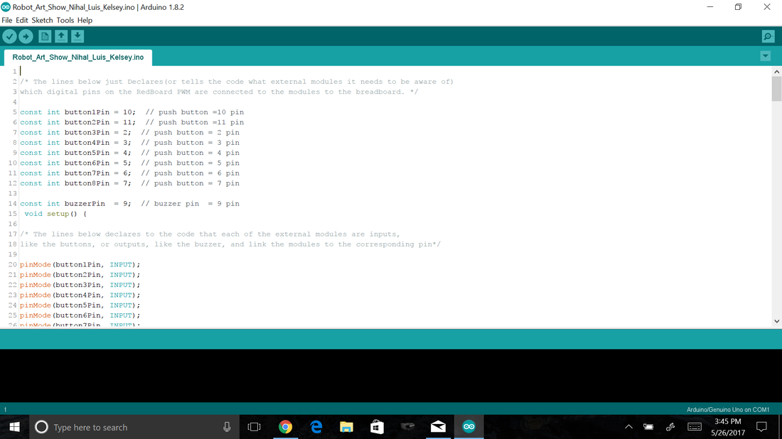
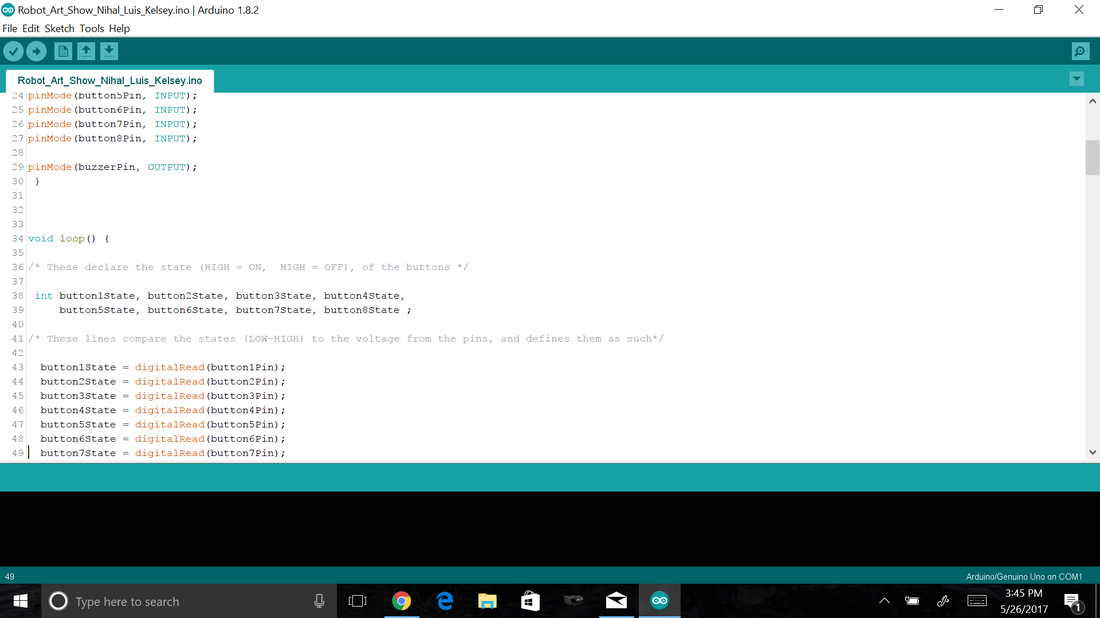
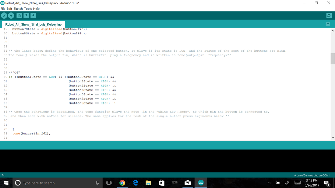

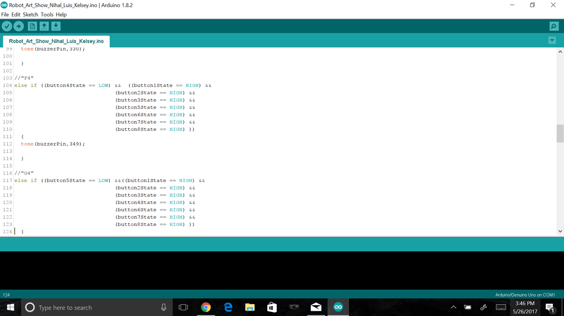
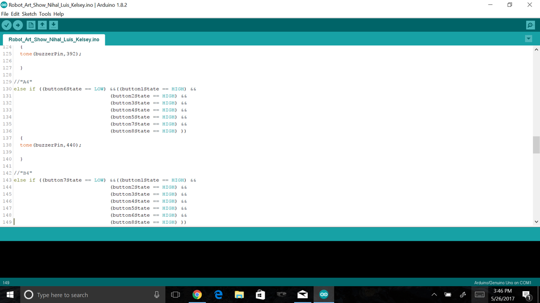
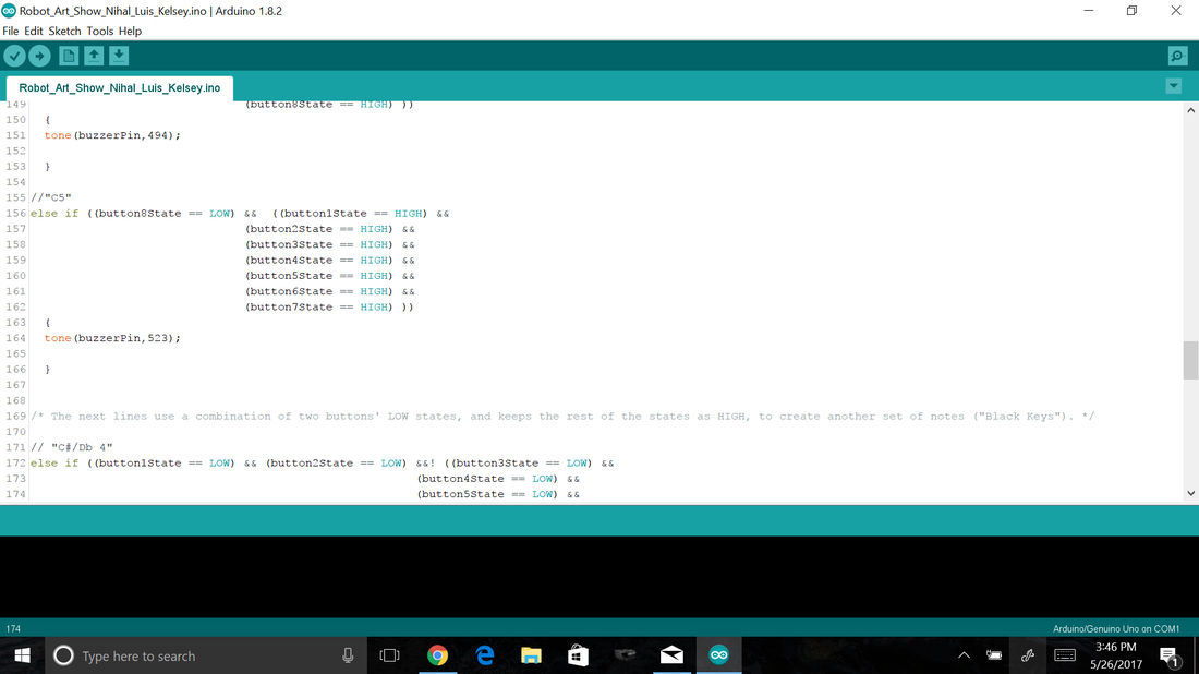
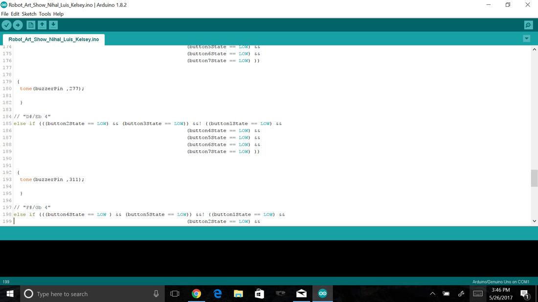
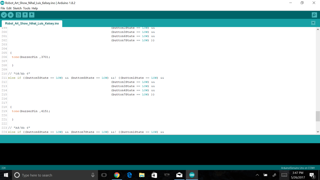
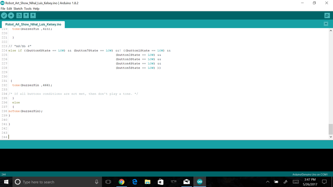
For the code, we first declared all of our variables, and then used else if statements to tell the buzzer when to play which notes. In the end, it did not work, but it did work in a computer simulation, so we suspect one of the buttons was broken.
Content
Circuit - a circuit is a loop of conductive material from one terminal to the other.
Series circuit - a series circuit is when the components of a circuit are connected so that the electricity has to flow through all of the components. In a series circuit, voltage splits in proportion to resistance and current is the same throughout the entire circuit.
Parallel circuit - a parallel circuit is when the components of a circuit are on separate branches that then separate and rejoin at the battery terminals. In a parallel circuit, voltage is the same on all pathways and current splits inversely to resistance.
Current - current is the flow of charge or electricity through a circuit.
Resistance - resistance is an obstacle to the current that slows it down, the quantity of slowing.
Resistor - An electrical component that adds resistance to a circuit. Because every circuit needs some resistance, virtually every circuit that we built had resistors in it.
Ohm's law - Ohm's law, V=IR, states that the voltage in a circuit is equal to the product of the total resistance and the total current.
Breadboard - a breadboard is a board on which complex circuits can be built temporarily. It consists of lots of holes that are connected by conductive material in rows.
Potentiometer - An electrical component that acts as a variable resistor.
LED - A type of light source that stands for Light Emitting Diode
Capacitor - an electrical component that holds charge, and then releases it.
RGB LED - an LED that can display any color, not just red, green or blue.
Button - a simple input that is just a simple switch. This was our choice of input for our piano.
Photoresistor - An input device that senses light.
Temperature sensor - An input device that senses temperature.
Flex sensor - An input device in that senses when it is bent.
DC motor - A motor that uses electric current to run.
Servo - Another type of motor that doesn't continuously spin but is controlled by inputting positions that it can take.
Buzzer - A device that can be used to make a sound or song. We used this in our project to play the notes.
Relay - A mechanical switch that allows two circuits to be electrically isolated but still able to exchange information.
Shift Register - A type of integrated circuit that lets the Arduino have more outputs.
LCD display - A display that can be programmed to show text or a picture.
VoidSetup - This is one of the functions that has to be in a code sketch. In it you put anything that you want the code to only do once.
VoidLoop - this is the other function that needs to be in a code sketch. In it you put anything that you want the code to loop.
PinMode - This function lets you bind specific pins to specific functions.
Reflection
I learned a lot during this project and I enjoyed it a lot. I think that i did some things well and other things not so well. One thing that I did well was cooperate with my group. We always came up with ideas together and split up the work well. We also came up with a very unique project, which no other group thought of, and we did a good job commenting our code and making it easy to understand. There were also some things that we didn't do so good though, one was getting everything done on time, we barely got everything done. Next time I will make sure that this won't happen. Also, we didn't prepare enough for our presentation. I will make sure my presentation is well prepared. Lastly, I want to improve on my leadership skills, I want to drive the discussion more and give more ideas.
